
How geomechanics risk assessment identifies TBM ground instability
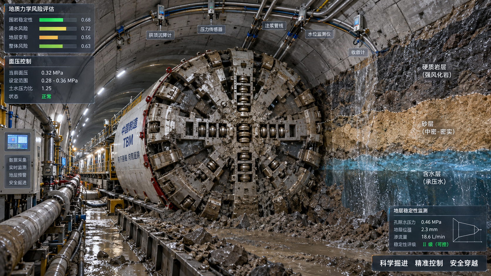
A geomechanics risk assessment identifies TBM ground instability by converting uncertain subsurface conditions into operational triggers: where face support may be inadequate, where the ground may deform beyond tolerance, where cutters may be overloaded, and where water pressure can change the failure mechanism. Its value is not limited to describing geology before excavation. It provides a decision framework that links ground behaviour to TBM configuration, operating limits, monitoring requirements, contingency measures, and schedule exposure.
For a tunnel project, the critical question is rarely whether difficult geology exists. It is whether the available ground model is detailed enough to predict how that geology will behave once it is unloaded, pressurized, cut, conditioned, and supported by the TBM. A rock mass that appears competent in borehole core can spall under high in-situ stress. A cohesive soil may remain stable at rest but become highly sensitive to changes in groundwater pressure or excavation-induced stress relief. A mixed-face reach may create asymmetric loading that neither a simple geological profile nor a generic machine specification can adequately represent.
Ground instability is a behaviour problem, not only a geological description
Geological logs identify materials, discontinuities, weathering grades, faults, and groundwater observations. A geomechanics risk assessment goes further by asking how these conditions interact with the excavation process. It evaluates the likelihood and consequence of specific instability mechanisms rather than treating “poor ground” as a single risk category.
For TBM works, the principal mechanisms often include face instability, chimneying or running ground above the shield, excessive convergence, squeezing, rock spalling, rockburst potential, block fall from discontinuities, settlement at the surface, inflow or blowout, and clogging that disrupts pressure control. These mechanisms can coexist. A fault zone, for example, may combine fractured rock, fine-grained infill, high permeability contrasts, and localized stress changes. The operational response required for that zone is therefore more complex than simply reducing penetration rate.
A useful assessment distinguishes between the ground’s inherent characteristics and its excavation response. Strength, stiffness, permeability, abrasivity, stress state, and joint orientation are inherent or measurable properties. Face extrusion, cutterhead blockage, shield jamming, crown settlement, and cutter damage are responses arising from the interaction of those properties with machine geometry and operational choices.
Building the ground model that a TBM team can use
Instability is commonly missed when project information remains divided between geology reports, laboratory data, hydrogeological studies, and machine operating records. The assessment should integrate these sources into a three-dimensional engineering ground model aligned with the proposed tunnel alignment, depth, cover, cross-passages, shafts, interfaces, and sensitive assets.
The model needs more than a chainage-based lithology sequence. It should identify the spatial uncertainty of fault zones, weak seams, boulders, karst features, old workings, permeable horizons, and mixed-face transitions. Boreholes provide point observations; the assessment must establish what can reasonably be inferred between them and what remains uncertain. Treating an interpolated boundary as a confirmed condition creates false precision and can lead to unpreparedness when the TBM encounters a materially different face.
In rock tunnelling, the assessment examines intact rock strength alongside rock-mass structure. Joint persistence, aperture, infill, spacing, orientation, and groundwater condition influence whether the cutterhead encounters a stable mass, removable blocks, or a heavily fractured zone. In high-cover tunnels, in-situ stresses require equal attention. The orientation and magnitude of principal stresses relative to the tunnel axis can indicate whether stress-induced spalling, slabbing, or sudden brittle failure is plausible at the crown, sidewalls, or face.
In soft ground, the parameters that matter most depend on the expected failure mode. Undrained shear strength and sensitivity are important in clays; permeability and density affect response in sands and gravels; fines content and plasticity influence conditioning and clogging. Groundwater cannot be reduced to a recorded water level. The relevant issue is pore-water pressure at tunnel depth, its likely variation across strata, and the hydraulic connection between the excavation chamber and surrounding ground.
Face stability: translating mechanics into support-pressure decisions
For EPB and slurry TBMs, face stability assessment defines the pressure envelope within which the machine can operate. The lower bound must prevent face movement, inflow, and ground loss. The upper bound must avoid excessive heave, blowout, or overpressurization of the ground. Neither limit is constant along the route.
The required support pressure changes with overburden, soil unit weight, groundwater pressure, shear strength, stratigraphic variability, and nearby structures. It is also affected by the effective support provided at the face. In an EPB machine, the chamber pressure is only meaningful if conditioned muck forms a sufficiently uniform, low-permeability plastic plug and if extraction through the screw conveyor is controlled. In a slurry TBM, pressure transmission depends on slurry properties, filter-cake development, permeability, and separation-system performance. A recorded chamber-pressure value alone is not proof of effective face support.
Mixed ground is particularly demanding because the support medium may behave differently across the face. A permeable sand layer on one side and stiff clay or weathered rock on the other can produce uneven pressure transmission and differential excavation. The risk assessment should identify these reaches before the TBM arrives and define how operating parameters will be adjusted: allowable pressure range, cutterhead speed, advance rate, torque limits, conditioning approach, screw conveyor control, and criteria for stopping advance.
Pressure targets also need to be connected to surface and subsurface observations. If settlement develops while the face remains nominally within the calculated pressure range, the cause may lie in inadequate tail-void filling, shield overcut, steering correction, loss of fines, or a local preferential flow path. The response should not automatically be to raise face pressure; doing so without identifying the mechanism may introduce uplift or increase clogging.
Stress-driven hazards in hard rock are often underestimated
Hard rock conditions can create a misleading sense of security because the tunnel face may appear stable during initial advance. At depth, high tangential stresses around the excavation can exceed the rock mass capacity after stress redistribution. This can cause progressive spalling, slabbing, or localized failure behind the cutterhead. In stronger and more brittle rock, stored strain energy may create dynamic failure concerns that require a dedicated assessment rather than reliance on conventional rock-mass classifications alone.
The geomechanical model should compare estimated in-situ stress conditions with rock strength, deformation modulus, structural geology, tunnel geometry, and excavation sequence. The result is not a precise prediction of every failure event. It is a defensible classification of where stress-related damage is plausible, how it could affect machine operations, and what monitoring or support provisions are justified.
For a TBM, these hazards affect more than worker safety. Spalling fragments can enter the cutterhead, obstruct muck flow, damage tools, and increase interventions. Convergent ground can load the shield skin, reduce annular clearance, and contribute to entrapment. The assessment should therefore link the anticipated deformation pattern to shield taper, articulation capability, probe-drilling needs, lubrication arrangements, segmental lining capacity, and recovery planning.
Water changes both the failure mechanism and the consequences
Groundwater is a primary driver of instability because it reduces effective stress, mobilizes fines, transports material into the excavation, and can create large pressure gradients through local defects or permeable features. The risk is not confined to high inflow volumes. Even limited inflow can destabilize a granular face, soften clayey materials, degrade conditioning performance, or cause loss of slurry circulation.
A meaningful hydrogeological assessment identifies aquifers, aquitards, fractured zones, recharge conditions, hydraulic boundaries, and the uncertainty attached to each. It should consider whether dewatering is permitted and technically viable, whether pressure relief could affect adjacent structures or settlements, and whether water chemistry may influence slurry, grout, corrosion protection, or treatment requirements.
Probe drilling ahead of the face is particularly valuable where the model indicates faults, karst, water-bearing fractures, or uncertain ground contacts. Its purpose is not merely to detect water. It provides an opportunity to verify ground class, estimate hydraulic response, and decide whether pre-grouting, modified excavation parameters, drainage controls, or a temporary hold point is needed before entering the zone.
Machine data becomes useful only when interpreted against the ground model
TBMs generate large volumes of operating data: thrust, torque, penetration, cutterhead rotation, chamber pressure, screw speed, slurry flow, density, volume balance, articulation, steering corrections, and ring-build records. These signals become early-warning indicators only when they are assessed as trends against expected ground behaviour.
A rising torque-to-penetration relationship can indicate harder ground, increased friction, cutter wear, blocky material, or clogging. A sudden reduction in torque may indicate a weak zone, void, open fracture, or loss of effective contact. Increased thrust with declining advance can point to shield friction, squeezing, poor muck transport, inadequate conditioning, or tool deterioration. No single parameter provides a reliable diagnosis in isolation.
Volume balance is especially important in soft ground. Discrepancies between theoretical excavation volume, removed spoil, injected grout, and observed settlement may reveal over-excavation, loss of material, poor annulus filling, or measurement errors that need investigation. The assessment should establish which parameter combinations are meaningful for each expected ground class and define escalation thresholds based on deviation from baseline behaviour, not on generic alarm values copied from another project.
Instrumentation outside the machine completes the feedback loop. Surface settlement points, extensometers, piezometers, inclinometers, building monitoring, and convergence measurements can validate whether the excavation response matches the model. Their value depends on installation location, reading frequency, baseline condition, and clear ownership of the response when trigger levels are exceeded.
Risk registers should lead to actions at the tunnel face
A risk register is useful only if each material risk has an operational consequence. “Faulted ground” is not a workable control measure. A better entry identifies the expected mechanism, warning signs, decision authority, immediate controls, and recovery options. For example, a permeable fault zone may require confirmation drilling at a defined distance ahead of the face, review of water-pressure readings, pre-agreed grouting materials, revised slurry properties or EPB conditioning, and a hold point before full entry.
Risk ownership should also be explicit. Design teams may maintain the baseline model, while the contractor controls machine operations and monitoring. The interface must specify how new observations revise the model, who authorizes changes to the support-pressure envelope, and how departures from the anticipated ground condition are recorded. Without this process, valuable excavation evidence can remain confined to daily production reports rather than improving the forward risk forecast.
Geotechnical Baseline Reports, where used in the contract structure, can provide a disciplined statement of the ground conditions assumed for design and risk allocation. They do not eliminate uncertainty, but they help separate expected variability from materially differing conditions. The geomechanics assessment should remain a living technical document throughout construction; it should be updated as probe holes, cutter changes, muck characteristics, instrumentation, and face mapping reveal conditions not resolved by the original investigation.
Common assessment failures
The most damaging mistake is treating the assessment as a pre-construction deliverable rather than a control system. Ground interpretation inevitably changes during excavation. If updated observations do not alter operating assumptions, the project retains the risk profile of an obsolete model.
Another failure is relying too heavily on classification systems. Rock-mass ratings and soil descriptions are useful communication tools, but they do not replace analysis of stress orientation, groundwater, discontinuity geometry, excavation diameter, lining sequence, or machine-ground interaction. A ground class should support a decision, not substitute for one.
It is also risky to define mitigation measures without checking implementation capacity. A plan that calls for pre-grouting, frequent probe drilling, altered conditioning, or rapid intervention is only credible if the machine has the required ports and equipment, crews are trained, materials are available, and the programme includes realistic time for the activity. Mitigation that cannot be deployed at the face is not a control.
What a robust assessment delivers
The practical output of a geomechanics risk assessment is a set of testable expectations. It states where instability may occur, what mechanism is expected, which machine and monitoring signals should change first, what operating envelope applies, and when escalation is mandatory. It also identifies the uncertainty that remains unresolved so that contingency planning is proportional rather than improvised.
That approach improves more than safety performance. It allows schedule forecasts to reflect the likelihood of slower advance, investigations, cutter interventions, pressure adjustments, and ground-treatment works in defined reaches. It supports earlier decisions on spare cutter stock, treatment materials, instrumentation, specialist support, and access arrangements. Most importantly, it prevents the project from discovering a ground-behaviour problem only after it has become a face-loss, settlement, machine-damage, or recovery event.
Rleated News
- How geomechanics risk assessment identifies TBM ground instabilityTime : Oct 11, 2026
- How cutterhead design affects TBM performance in mixed groundTime : Oct 09, 2026
- What causes excessive disc cutter wear in variable-ground TBM tunneling?Time : Sep 11, 2026
Industry Briefing
Get the top 5 industry headlines delivered to your inbox every morning.